
H3C S7500E Series Ethernet Switches Installation Manual


Installation Manual
H3C S7500E Series Ethernet Switches Chapter 3 Hardware Installation
3-13
Table 3-1 Console cable pinouts
Pin (RJ-45) Signal Pin (DB-9) Signal
1 RTS 8 CTS
2 DTR 6 DSR
3 TXD 2 RXD
4 SG 5 SG
5 SG 5 SG
6 RXD 3 TXD
7 DSR 4 DTR
8 CTS 7 RTS
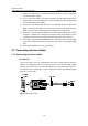
II. Connecting the console cable
Take the following steps to connect the console cable, when configuring the switch on
the terminal.
1) Plug the DB-9 female plug of the console cable to the serial port of the PC or the
terminal where the switch is to be configured.
2) Connect the RJ-45 connector of the console cable to the console port of the
switch.
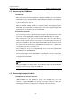
3.7.2 Connecting the AUX Cable (Optional)
The AUX cable is used for the remote Modem dial-up configuration for the S7500E
series.
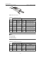
I. Introduction
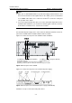
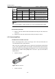
The AUX cable is an 8-core shielded cable. One end is an RJ-45 RS-232 connector,
which can be plugged into the console port. The other end is furnished with a DB-9
connector, which can be plugged into the DB-9 socket on the Modem. The AUX cable is
the same as the console cable. For details, see
Figure 3-14 and Table 3-1.
II. Connection procedure
Follow these steps to connect the AUX cable:
1) Plug the RJ-45 connector of the AUX cable into the console port.
2) Plug the DB-9 connector of the AUX cable into the serial port of the analog
Modem.