
H3C S7500E Series Ethernet Switches Installation Manual

Installation Manual
H3C S7500E Series Ethernet Switches Chapter 3 Hardware Installation
3-17
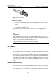
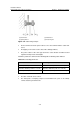
Figure 3-17 LC connector
II. Connecting fibers
1) Remove the protective cap from the connector of the fiber and clean the surface of
the fiber.
2) Remove the protective cap from the optical interface of the switch, and plug one
end of the fiber into this interface.
Step 3: Connect the other end of the fiber connector to the corresponding device.
Caution:
When the optical interface has not been connected with a fiber connector or its
dustproof cover is open, there might be some invisible radiation emitted from the optical
interface. So do not stare into the optical interface directly.
Cover the optical interface if there is no connector plugged in.
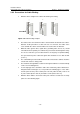
3.8 Cabling
3.8.1 Workbench-Mounted Switch
For an integrated chassis, you do not have to care about the cabling inside or outside
the cabinet. All the interface service cables of the S7500E series except the S7506E-V
run on the left side of the chassis, but the interface service cables of the S7506E-V run
on the upward or downward cabling racks. The power cables (including AC and DC
power cables) of the S7500E series except the S7502E and S7503E-S run out of the
front of the chassis, but those of the S7502E and S7503E-S run out of the rear of the
chassis.
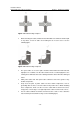
3.8.2 Rack-Mounted Switch
For the switches mounted in a 19” standard cabinet or N68 cabinet, the service cables
are bound on the cable binding rack at the left side of the chassis and arranged to run
on the cabling rack or in the raised floor according to the situation in an exchange