
H3C S7500E Series Ethernet Switches Installation Manual

Installation Manual
H3C S7500E Series Ethernet Switches Chapter 5 Hardware Maintenance
5-5
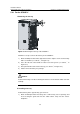
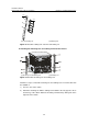
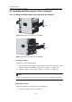
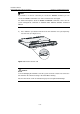
5.3.2 Installing a Card
Install a card in the opposite way you remove it:
1) Wear an ESD-preventive wrist strap and loosen the captive screws on the blank
panel on the slot, where the card should be inserted.
2) Hold the card by the front panel with one hand and hold the card bottom with the
other hand (do not touch its circuit). Slide the card steadily into the slot along the
guide rails. When most part of the card is inserted in the slot, press the ejector
levers on the card outward with both hands. Then, push the card until the
positioning pin on its handle bar touches the hole on the chassis.
3) Press the ejector levers inward until the ejector levers touch the panel tightly and
the card snaps into the backplane.
4) Tighten the captive screws to fix the card.
Note:
Put away the removed blank panel for future use.
When installing or removing a card, keep the card parallel to the slot to prevent the card
from scratching other parts in the chassis.
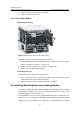
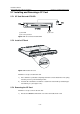
5.4 Removing and Installing a Fan Tray
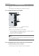
Caution:
Do not touch any naked wire, terminal or any part of the product labeled with a
dangerous voltage to avoid injury.
If you want to replace the fan tray of an in-service switch, separate the fan tray from the
backplane to disconnect the power and wait for the fan stops rotating before pulling it
out completely. Considering that the fan may be still rotating, avoid stretching your
hands into the fan tray.
The fan tray handle of the S7506E-V is slightly different from those of the S7502E,
S7503E-S, S7503E, S7506E, and S7510E. The fan tray handles of S7502E, S7503E-S,
S7503E, S7506E, and S7510E are fixed, while that of the S7506E-V is hidden in the
groove of the fan tray. Therefore, you need to rotate the handle out of the groove before
removing the fan tray from the S7506E-V or installing a fan tray on the S7506E-V.