
H3C S7500E Series Ethernet Switches Installation Manual

Installation Manual
H3C S7500E Series Ethernet Switches Chapter 1 Product Overview
1-7
(3)
(5)
(4)
(4)
(3)
(1)
(2)
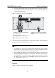
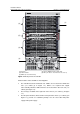
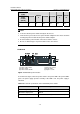
(1) Fan tray (2) Jack for ESD-preventive wrist strap
(3) Power module (4) LPUs (in slot 0 to slot 4 and slot 7 to slot 11)
(5) SRPUs (in slot 5 and slot 6)
Figure 1-7 Front panel of the S7510E
All the modules of the S7510E are hot swappable.
z The S7510E has twelve horizontal slots. SRPUs are inserted in the middle two
slots (see callout (5) in
Figure 1-7). SRPUs are required and support
active-standby switchover. Different LPUs are inserted in the other ten slots (see
callout (4) in
Figure 1-7).
z The fan tray is installed on the right side of the chassis (see callout (1) in Figure
1-7).
z The two power modules, which sit in the lower part of the chassis (see callout (3) in
Figure 1-7), provide 1+1 redundancy backup. You can select either AC power
supply or DC power supply.