
H3C S7500E Series Ethernet Switches Installation Manual

Installation Manual
H3C S7500E Series Ethernet Switches Chapter 7 Troubleshooting
7-3
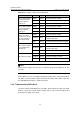
Table 7-1 Description of LEDs on the PSR1400-A
Case LED Color Status
INPUT Green The power input is normal.
OUTPUT Red No power is output.
The power module is
connected but the
power switch is
turned off.
FAN Red The power module fan does not rotate.
INPUT Green The power input is normal.
OUTPUT Green The power output is normal.
The power module is
connected and the
power switch is
turned on.
FAN Green The power module fan works normally.
INPUT Green The power input is normal.
OUTPUT Red
The power module goes into the
self-protection state.
There is a short
circuit, over-current,
or over voltage on
the output circuit.
FAN Green The power module fan works normally.
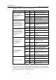
INPUT Green The power input is normal.
OUTPUT Red
The power module goes into the
self-protection state.
The power module is
over-temperature
protected.
FAN Green The power module fan works normally.
INPUT Green The power input is normal.
OUTPUT Green The power output is normal.
The fan tray is faulty.
FAN Red The power module fan is faulty.
Note:
After the power supply is cut off, it takes a short while for the power LED to go off. This
is normal.
On the SRPUs, there are also LEDs indicating the working status of the power modules.
For details, refer to related description about the power LEDs on the SRPUs other than
the LSQ1MPUA0 in Chapter 1 “Product Overview”.
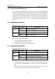
7.2.4 Troubleshooting PSR1400-D
The power module PSR1400-D has four LEDs, which indicate the input and output
statuses of the power module and the working statuses of the power module fan and
the PoE power supply, respectively.