
H3C S7500E Series Ethernet Switches Installation Manual

Installation Manual
H3C S7500E Series Ethernet Switches Chapter 1 Product Overview
1-9
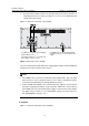
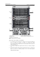
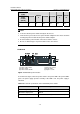
active-standby switchover. Different LPUs are inserted in the other six slots (see
callout (2) in
Figure 1-8).
z The fan tray is installed above the SRPUs and LPUs (see callout (1) in Figure 1-8)
and the air flows up from the bottom.
z The two power modules, which sit in the lower part of the chassis (see callout (3) in
Figure 1-8), provide 1+1 redundancy backup. You can select either AC power
supply or DC power supply.
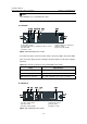
1.2.2 Backplane
The backplane in the integrated chassis of the S7500E series implements high-speed
data exchange as well as management & control signal exchange between SRPUs and
LPUs.
The backplane mainly provides the following functions:
z Interconnection between cards
z Card hot-swapping
z Automatic slot recognition
z Automatic chassis type recognition
z Distributed power supply to the system. The S7506E-V has two backplanes:
signal backplane and power supply backplane. The power supply backplane is
connected to the power modules and is also connected to the signal backplane
with an internal cable.
z Connection of the signal cable that monitors the fan tray and power supply
1.2.3 Power Supply System
The S7500E series support a variety of power modules, as listed in Table 1-3.
Table 1-3 Power module models of the S7500E series
Model Height
Power input
mode (AC/DC)
Support PoE
power (Yes/No)
PSR320-A 1 U AC No
PSR320-D 1 U DC No
PSR650-A 1 U AC No
PSR650-D 1 U DC No
PSR1400-A 3 U AC No
PSR1400-D 3 U DC No
PSR2800-ACV 3 U AC No