
H3C S7500E Series Ethernet Switches Installation Manual

Installation Manual
H3C S7500E Series Ethernet Switches Chapter 1 Product Overview
1-11
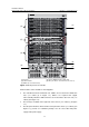
Chassis
(right)
Power
module
(below)
S7502E
S7503E-
S
S7503E S7506E
S7506E-
V
S7510
E
PSR2800-AC
V
N N Y1 Y1 Y1 Y1
Note:
z Y1 means that the power module directly fits the chassis.
z Y2 means that you need to insert a power module adapter into the chassis and then
inserting the power module into the power module adapter.
z N means that the power module cannot be used in the chassis.
z Do not use different types of power modules in the same device.
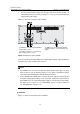
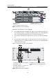
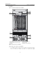
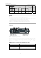
I. PSR320-A
(1) Power cable retainer (2) AC power socket
(3) Power switch (4) Power LED
(5) Power module handle (6) Captive screws
Figure 1-9 PSR320-A power module
As shown in the figure, above the power switch is the power LED. If the power LED is
green, the power supply operates normally. If the LED is red, the power supply is
abnormal.
Table 1-6 Technical specifications of the PSR320-A power module
Item Specifications
Rated voltage range 100 VAC to 240 VAC; 50 Hz or 60 Hz
Maximum output power 300 W
Dimensions (H × W × D) 40 × 140 × 350 mm (1.57 × 5.51 × 13.78 in.)