
H3C S7500E Series Ethernet Switches Installation Manual

Installation Manual
H3C S7500E Series Ethernet Switches Chapter 1 Product Overview
1-15
VI. PSR1400-D
(8)
(6)
(4)
(5)
(3)
(7)
(2)
(1)
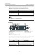
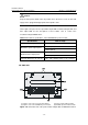
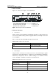
(1) Captive screws (2) COM port for monitoring PoE
(3) Power LEDs (4) Negative terminal (–) of DC input (–48 V to –60 V)
(5) RTN terminal (+) of DC input (6) Power module handle
(7) System power switch (8) PoE power switch
Figure 1-14 PSR1400-D power module
The PSR1400-D power module provides system power and PoE power. The switch
marked “SYSTEM” is used to control the system power, and the other marked “PoE” is
used to control the PoE power. The RJ-45 port (RS485) on the right of the PoE power
switch is the COM port for monitoring PoE.
Caution:
z If power to the PSR1400-D power module is switch controlled, make sure that the
negative input of the power module is disconnected when disconnecting power to
the power module.
z Keep the PoE power switch in the off position unless the device needs to offer PoE
supply and is equipped with appropriate PoE-capable cards.
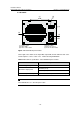
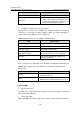
On the right of the panel are the input LED, output LED, fan LED and PoE LED. For
their colors and descriptions, refer to section 7.2.4 “Troubleshooting PSR1400-D.”