
H3C S7500E Series Ethernet Switches Installation Manual

Installation Manual
H3C S7500E Series Ethernet Switches Chapter 1 Product Overview
1-21
III. Panel and LEDs
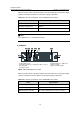
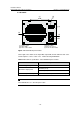
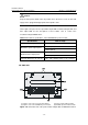
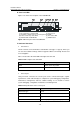
Figure 1-18 shows the front panel of the LSQ1MPUA0.
(1) CF card interface and CFS LED (2) Console port
(3) 10/100Base-TX Ethernet port for management and LEDs
(4) Power and fan tray status LEDs (5) LPU status LEDs
(6) ACTIVE LED of LSQ1MPUA0 (7) RESET button
Figure 1-18 Front panel of the LSQ1MPUA0
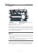
IV. On-board interfaces
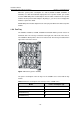
z CF card slot
The CF card slot can accommodate a standard CF card (Type I or Type II), where you
can store host software and logs, and thus upgrade software conveniently. The CF card
is hot swappable.
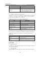
Table 1-16 describes the CFS LED on the right of the CF card.
Table 1-16 Description of the CFS LED
Status Description
OFF No CF card is in position.
ON The CF card is in position.
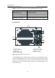
z Console port
Using an RJ-45 connector, the console port can be connected through a regular
asynchronous serial cable directly to a computer for system debugging, configuration,
maintenance, management, and host software loading, or to a modem for remote
system debugging, configuration, maintenance and management.
Table 1-17 Specifications of the console port
Item Specifications
Connector type RJ-45
Number of connectors 1
Interface standard Asynchronous EIA/TIA-232
Baud rate 115,200 bps (defaulting to 9,600 bps)