
H3C S7500E Series Ethernet Switches Operation Manual

Operation Manual – NTP
H3C S7500E Series Ethernet Switches Chapter 1 NTP Configuration
1-3
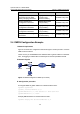
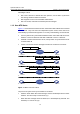
z When the NTP message leaves Switch B, Switch B timestamps it. The timestamp
is 11:00:02 am (T3).
z When Switch A receives the NTP message, the local time of Switch A is 10:00:03
am (T4).
Up to now, Switch A has sufficient information to calculate the following two important
parameters:
z The roundtrip delay of NTP message: Delay = (T
4
–T
1
) – (T
3
-T
2
) = 2 seconds.
z Time difference between Switch A and Switch B: Offset = ((T
2
-T
1
) + (T
3
-T
4
))/2 = 1
hour.
Based on these parameters, Switch A can synchronize its own clock to the clock of
Switch B.
This is only a rough description of the work mechanism of NTP. For details, refer to RFC
1305.
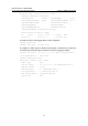
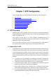
1.1.3 NTP Message Format
NTP uses two types of messages, clock synchronization message and NTP control
message. An NTP control message is used in environments where network
management is needed. As it is not a must for clock synchronization, it will not be
discussed in this document.
Note:
All NTP messages mentioned in this document refer to NTP clock synchronization
messages.
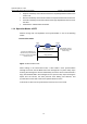
A clock synchronization message is encapsulated in a UDP message, in the format
shown in
Figure 1-2.