
H3C S7500E Series Ethernet Switches Operation Manual

Operation Manual – NTP
H3C S7500E Series Ethernet Switches Chapter 1 NTP Configuration
1-21
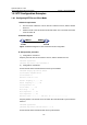
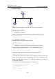
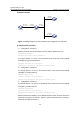
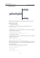
II. Network diagram
Switch A
Switch B Switch C
3.0.1.31/24
3.0.1.32/24 3.0.1.33/24
Figure 1-8 Network diagram for NTP symmetric peers mode configuration
III. Configuration procedure
1) Configuration on Switch A:
# Specify the local clock as the reference source, with the stratum level of 2.
<SwitchA> system-view
[SwitchA] ntp-service refclock-master 2
2) Configuration on Switch B:
# Specify Switch A as the NTP server of Switch B.
<SwitchB> system-view
[SwitchB] ntp-service unicast-server 3.0.1.31
3) Configuration on Switch C (after Switch B is synchronized to Switch A):
# Specify the local clock as the reference source, with the stratum level of 1.
<SwitchC> system-view
[SwitchC] ntp-service refclock-master 1
# Configure Switch B as a symmetric peer after local synchronization.
[SwitchC] ntp-service unicast-peer 3.0.1.32
In the step above, Switch B and Switch C are configured as symmetric peers, with
Switch C in the symmetric-active mode and Switch B in the symmetric-passive mode.
Because the stratus level of Switch C is 1 while that of Switch B is 3, Switch B is
synchronized to Switch C.
# View the NTP status of Switch B after clock synchronization.
[SwitchB] display ntp-service status
Clock status: synchronized
Clock stratum: 2
Reference clock ID: 3.0.1.33