
H3C S7500E Series Ethernet Switches Operation Manual

Operation Manual – NTP
H3C S7500E Series Ethernet Switches Chapter 1 NTP Configuration
1-27
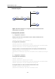
[SwitchA-Vlan-interface3] ntp-service multicast-client
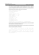
# View the NTP status of Switch A after clock synchronization.
[SwitchA] display ntp-service status
Clock status: synchronized
Clock stratum: 3
Reference clock ID: 3.0.1.31
Nominal frequency: 100.0000 Hz
Actual frequency: 100.0000 Hz
Clock precision: 2^7
Clock offset: 0.0000 ms
Root delay: 40.00 ms
Root dispersion: 10.83 ms
Peer dispersion: 34.30 ms
Reference time: 16:02:49.713 UTC Apr 25 2007 (C6D95F6F.B6872B02)
As shown above, Switch A has been synchronized to Switch C, and the clock stratum
level of Switch A is 3, while that of Switch C is 2.
# View the NTP session information of Switch A, which shows that an association has
been set up between Switch A and Switch C.
[SwitchA] display ntp-service sessions
source reference stra reach poll now offset delay disper
**************************************************************************
[1234] 3.0.1.31 127.127.1.0 2 255 64 26 -16.0 40.0 16.6
note: 1 source(master),2 source(peer),3 selected,4 candidate,5 configured
Total associations : 1
Note:
Refer to IGMP Configuration for how to configure IGMP.
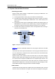
1.8.5 Configuring NTP Server/Client Mode with Authentication
I. Network requirements
z The local clock of Switch A is to be configured as a reference source, with the
stratum level of 2.
z Switch B works in the client mode and Switch A is to be used as the NTP server of
Switch B, with Switch B as the client.
z NTP authentication is to be enabled for Switch A and Switch B at the same time.