
H3C S7500E Series Ethernet Switches Operation Manual

Operation Manual – NTP
H3C S7500E Series Ethernet Switches Chapter 1 NTP Configuration
1-28
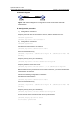
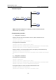
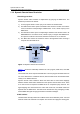
II. Network diagram
Figure 1-11 Network diagram for configuration of NTP server/client mode with
authentication
III. Configuration procedure
1) Configuration on Switch A:
# Specify the local clock as the reference source, with the stratum level of 2.
<SwitchA> system-view
[SwitchA] ntp-service refclcok-master 2
2) Configuration on Switch B:
<SwitchB> system-view
# Enable NTP authentication on Switch B.
[SwitchB] ntp-service authentication enable
# Set an authentication key.
[SwitchB] ntp-service authentication-keyid 42 authentication-mode md5
aNiceKey
# Specify the key as key as a trusted key.
[SwitchB] ntp-service reliable authentication-keyid 42
# Specify Switch A as the NTP server.
[SwitchB] ntp-service unicast-server 1.0.1.11 authentication-keyid 42
Before Switch B can synchronize its clock to that of Switch A, you need to enable NTP
authentication for Switch A.
Perform the following configuration on Switch A:
# Enable NTP authentication.
[SwitchA] ntp-service authentication enable
# Set an authentication key.
[SwitchA] ntp-service authentication-keyid 42 authentication-mode md5
aNiceKey
# Specify the key as key as a trusted key.
[SwitchA] ntp-service reliable authentication-keyid 42
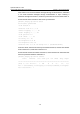
# View the NTP status of Switch B after clock synchronization.
[SwitchB] display ntp-service status
Clock status: synchronized