
H3C S7500E Series Ethernet Switches Operation Manual

Operation Manual – NTP
H3C S7500E Series Ethernet Switches Chapter 1 NTP Configuration
1-30
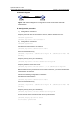
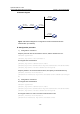
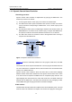
II. Network diagram
Vlan-int3
1.0.1.11/24
Vlan-int3
1.0.1.10/24
Vlan-int2
3.0.1.31/24
Vlan-int2
3.0.1.32/24
Vlan-int2
3.0.1.30/24
Switch A Switch B
Switch C
Switch D
Figure 1-12 Network diagram for configuration of NTP broadcast mode with
authentication (on switches)
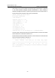
III. Configuration procedure
1) Configuration on Switch C:
# Specify the local clock as the reference source, with the stratum level of 3.
<SwitchC> system-view
[SwitchC] ntp-service refclock-master 3
# Configure NTP authentication
[SwitchC] ntp-service authentication enable
[SwitchC] ntp-service authentication-keyid 88 authentication-mode md5 123456
[SwitchC] ntp-service reliable authentication-keyid 88
# Specify Switch C as an NTP broadcast server, and specify an authentication key.
[SwitchC] interface vlan-interface 2
[SwitchC-Vlan-interface2] ntp-service broadcast-server authentication-keyid
88
2) Configuration on Switch D:
# Configure NTP authentication
<SwitchD> system-view
[SwitchD] ntp-service authentication enable
[SwitchD] ntp-service authentication-keyid 88 authentication-mode md5 123456
[SwitchD] ntp-service reliable authentication-keyid 88
# Configure Switch D to work in the NTP broadcast client mode
[SwitchD] interface vlan-interface 2
[SwitchD-Vlan-interface2] ntp-service broadcast-client