
H3C S7500E Series Ethernet Switches Operation Manual


Operation Manual – DNS
H3C S7500E Series Ethernet Switches Chapter 1 DNS Configuration
1-11
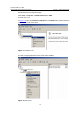
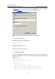
This configuration may vary with different DNS servers. When a Windows 2000 server
acts as the DNS server, refer to
Dynamic Domain Name Resolution Configuration
Example
for related configuration information.
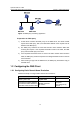
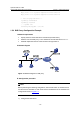
2) Configure the DNS proxy
# Specify the DNS server 4.1.1.1.
<SwitchA> system-view
[SwitchA] dns server 4.1.1.1
# Enable DNS proxy.
[SwitchA] dns proxy enable
3) Configure the DNS client
# Enable the domain name resolution function.
<SwitchB> system-view
[SwitchB] dns resolve
# Specify the DNS server 2.1.1.2.
[SwitchB] dns server 2.1.1.2
4) Configuration verification
# Execute the ping host.com command on Switch B to verify that the host can be
pinged after the host’s IP address 3.1.1.1 is resolved.
[SwitchB] ping host.com
Trying DNS resolve, press CTRL_C to break
Trying DNS server (2.1.1.2)
PING host.com (3.1.1.1):
56 data bytes, press CTRL_C to break
Reply from 3.1.1.1: bytes=56 Sequence=1 ttl=126 time=3 ms
Reply from 3.1.1.1: bytes=56 Sequence=2 ttl=126 time=1 ms
Reply from 3.1.1.1: bytes=56 Sequence=3 ttl=126 time=1 ms
Reply from 3.1.1.1: bytes=56 Sequence=4 ttl=126 time=1 ms
Reply from 3.1.1.1: bytes=56 Sequence=5 ttl=126 time=1 ms
--- host.com ping statistics ---
5 packet(s) transmitted
5 packet(s) received
0.00% packet loss
round-trip min/avg/max = 1/1/3 ms