
H3C S7500E Series Ethernet Switches Operation Manual


Operation Manual – HA
H3C S7500E Series Ethernet Switches Chapter 1 VRRP Configuration
1-3
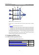
Host A
Host B
Host C
Switch A
Switch B
Switch C
Virtual router
Network
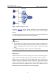
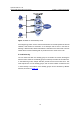
Figure 1-2 Network diagram for VRRP
As shown in
Figure 1-2, Switch A, Switch B, and Switch C form a virtual router, which
has its own IP address. Hosts on the Ethernet use the virtual router as the default
gateway.
The switch with the highest priority of the three switches is elected as the master switch
to act as the gateway, and the other two are backup switches.
Caution:
z The IP address of the virtual router can be either an unused IP address on the
segment where the standby group resides or the IP address of an interface on a
switch in the standby group. In the latter case, the switch is called the IP address
owner.
z In a VRRP standby group, there can only be one IP address owner.
I. VRRP priority
VRRP determines the role (master or backup) of each switch in the standby group by
priority. A switch with a higher priority has more opportunity to become the master.
VRRP priority is in the range of 0 to 255. A bigger number means a higher priority.
Priorities 1 to 254 are configurable. Priority 0 is reserved for special uses and priority
255 for the IP address owner. When a switch acts as the IP address owner, its priority
remains 255 and cannot be configured. That is, if there is an IP address owner in a
standby group, it acts as the master as long as it works properly.