
H3C S7500E Series Ethernet Switches Operation Manual


Operation Manual – HA
H3C S7500E Series Ethernet Switches Chapter 1 VRRP Configuration
1-8
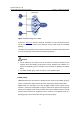
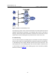
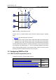
Figure 1-5 VRRP in master/backup mode
At the beginning, Switch A is the master and therefore can forward packets to external
networks, while Switch B and Switch C are backups and are thus in the state of
listening. If Switch A fails, Switch B and Switch C will elect for the new master. The new
master takes over the forwarding task to provide services to hosts on the LAN.
II. Load balancing
You can create more than one standby group on an interface of a switch, allowing the
switch to be the master of one standby group but a backup of another at the same time.
In load balancing mode, multiple switches provide services at the same time. This
mode requires two or more standby groups, each of which includes a master and one
or more backups. The masters of the standby groups can be assumed by different
switches, as shown in
Figure 1-6.