
H3C S7500E Series Ethernet Switches Operation Manual


Operation Manual – HA
H3C S7500E Series Ethernet Switches Chapter 1 VRRP Configuration
1-9
Host A
Host B
Host C
Switch A
Backup
Switch B
Backup
Switch C
Master
Virtual router 2
Virtual router 3Virtual router 1
Master
Backup
Backup Backup
Master
Backup
Network
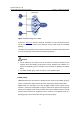
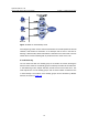
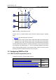
Figure 1-6 VRRP in load balancing mode
A switch can be in multiple standby groups and hold a different priority in different
group.
In
Figure 1-6, three standby groups are present:
z Standby group 1: Switch A is the master; Switch B and Switch C are the backups.
z Standby group 2: Switch B is the master; Switch A and Switch C are the backups.
z Standby group 3: Switch C is the master; Switch A and Switch B are the backups.
For load balancing among Switch A, Switch B, and Switch C, hosts on the LAN need to
be configured to use standby group 1, 2, and 3 as the default gateways respectively.
When configuring VRRP priorities, ensure that each switch holds such a priority in each
standby group that it will take the expected role in the group.
1.2 Configuring VRRP for IPv4
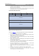
1.2.1 VRRP for IPv4 Configuration Task List
Complete these tasks to configure VRRP for IPv4:
Task Remarks
Enabling Users to Ping Virtual IP Addresses Optional
Configuring the Association Between Virtual IP Address and
MAC Address
Optional
Creating Standby Group and Configuring Virtual IP Address Required