
H3C S7500E Series Ethernet Switches Operation Manual

Operation Manual – HA
H3C S7500E Series Ethernet Switches Chapter 1 VRRP Configuration
1-22
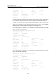
IPv4 Standby Information:
Run Method : VIRTUAL-MAC
Virtual IP Ping : Enable
Interface : Vlan-interface2
VRID : 1 Adver. Timer : 1
Admin Status : UP State : Backup
Config Pri : 100 Run Pri : 100
Preempt Mode : YES Delay Time : 5
Auth Type : NONE
Virtual IP : 202.38.160.111
Master IP : 202.38.160.1
The above information indicates that in standby group 1 Switch A is the master, Switch
B is the backup and packets sent from Host A to Host B are forwarded by Switch A.
If Switch A fails, you can still ping through Host B on Host A. Use the display vrrp
command to view the detailed information of the standby group on Switch B.
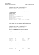
# If Switch A fails, the detailed information of standby group 1 on Switch B is displayed.
[SwitchB-Vlan-interface2] display vrrp verbose
IPv4 Standby Information:
Run Method : VIRTUAL-MAC
Virtual IP Ping : Enable
Interface : Vlan-interface2
VRID : 1 Adver. Timer : 1
Admin Status : UP State : Master
Config Pri : 100 Run Pri : 100
Preempt Mode : YES Delay Time : 0
Auth Type : NONE
Virtual IP : 202.38.160.111
Virtual MAC : 0000-5e00-0101
Master IP : 202.38.160.2
The above information indicates that if Switch A fails, Switch B becomes the master,
and packets sent from Host A to Host B are forwarded by Switch B.
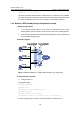
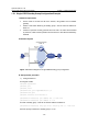
1.4.2 VRRP Interface Tracking Configuration Example
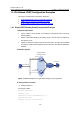
I. Network requirements
z Host A needs to access Host B on the Internet, using 202.38.160.111/24 as its
default gateway.
z Switch A and Switch B belong to standby group 1 with the virtual IP address of
202.38.160.111.
z If Switch A operates normally, packets sent from Host A to Host B are forwarded
by Switch A; if Switch A is in work, but its VLAN-interface 3 which connects to the