
H3C S7500E Series Ethernet Switches Operation Manual

Operation Manual – HA
H3C S7500E Series Ethernet Switches Chapter 1 VRRP Configuration
1-23
Internet is not available, packets sent from Host A to Host B are forwarded by
Switch B.
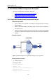
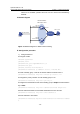
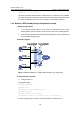
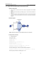
II. Network diagram
Host A
Switch A
Switch B
Virtual IP address:
202.38.160.111/24
Vlan-int2
202.38.160.1/24
Vlan-int2
202.38.160.2/24
Host B
202.38.160.3/24
203.2.3.1/24
Vlan-int3
Internet
Figure 1-8 Network diagram for VRRP interface tracking
III. Configuration procedure
1) Configure Switch A
# Configure VLAN 2.
<SwitchA> system-view
[SwitchA] vlan 2
[SwitchA-vlan2] port GigabitEthernet 2/0/5
[SwitchA-vlan2] quit
[SwitchA] interface vlan-interface 2
[SwitchA-Vlan-interface2] ip address 202.38.160.1 255.255.255.0
# Create a standby group 1 and set its virtual IP address to 202.38.160.111.
[SwitchA-Vlan-interface2] vrrp vrid 1 virtual-ip 202.38.160.111
# Configure the priority of Switch A in the standby group to 110.
[SwitchA-Vlan-interface2] vrrp vrid 1 priority 110
# Configure the authentication mode of the standby group to simple and authentication
key to hello.
[SwitchA-Vlan-interface2] vrrp vrid 1 authentication-mode simple hello
# Set the interval for Master to send VRRP advertisement to five seconds.
[SwitchA-Vlan-interface2] vrrp vrid 1 timer advertise 5
# Set the interface to be tracked.
[SwitchA-Vlan-interface2] vrrp vrid 1 track interface vlan-interface 3 reduced
30