
H3C S7500E Series Ethernet Switches Operation Manual

Operation Manual – HA
H3C S7500E Series Ethernet Switches Chapter 1 VRRP Configuration
1-24
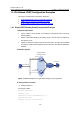
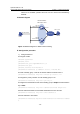
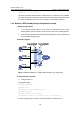
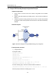
2) Configure Switch B
# Configure VLAN 2.
<SwitchB> system-view
[SwitchB] vlan 2
[SwitchB-vlan2] port GigabitEthernet 2/0/5
[SwitchB-vlan2] quit
[SwitchB] interface vlan-interface 2
[SwitchB-Vlan-interface2] ip address 202.38.160.2 255.255.255.0
# Create a standby group 1 and set its virtual IP address to 202.38.160.111.
[SwitchB-Vlan-interface2] vrrp vrid 1 virtual-ip 202.38.160.111
# Configure the authentication mode of the standby group to simple and authentication
key to hello.
[SwitchB-Vlan-interface2] vrrp vrid 1 authentication-mode simple hello
# Set the interval for Master to send VRRP advertisement to five seconds.
[SwitchB-Vlan-interface2] vrrp vrid 1 timer advertise 5
3) Verify the configuration
After the configuration, Host B can be pinged through on Host A. You can use the
display vrrp command to verify the configuration.
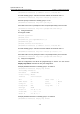
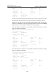
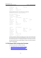
# Display detailed information of standby group 1 on Switch A.
[SwitchA-Vlan-interface2] display vrrp verbose
IPv4 Standby Information:
Run Method : VIRTUAL-MAC
Virtual IP Ping : Enable
Interface : Vlan-interface2
VRID : 1 Adver. Timer : 5
Admin Status : UP State : Master
Config Pri : 110 Run Pri : 110
Preempt Mode : YES Delay Time : 0
Auth Type : SIMPLE TEXT Key : hello
Track IF : Vlan3 Pri Reduced : 30
Virtual IP : 202.38.160.111
Virtual MAC : 0000-5e00-0101
Master IP : 202.38.160.1
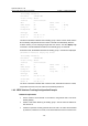
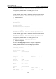
# Display detailed information of standby group 1 on Switch B.
[SwitchB-Vlan-interface2] display vrrp verbose
IPv4 Standby Information:
Run Method : VIRTUAL-MAC
Virtual IP Ping : Enable
Interface : Vlan-interface2