
H3C S7500E Series Ethernet Switches Operation Manual

Operation Manual – HA
H3C S7500E Series Ethernet Switches Chapter 1 VRRP Configuration
1-26
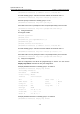
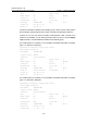
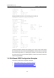
Master IP : 202.38.160.2
The above information indicates that if VLAN-interface 3 on Switch A is not available,
the priority of Switch A is reduced to 80 and it becomes the backup. Switch B becomes
the master and packets sent from Host A to Host B are forwarded by Switch B.
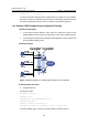
1.4.3 Multiple VRRP Standby Group Configuration Example
I. Network requirements
z In the segment 202.38.160.0/24, some hosts use 202.38.160.111/24 as their
default gateway and some hosts use 202.38.160.112/24 as their default gateway.
z Load sharing and mutual backup between default gateways can be implemented
by using VRRP standby groups.
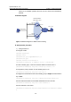
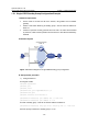
II. Network diagram
Figure 1-9 Network diagram for multiple VRRP standby group configuration
III. Configuration procedure
1) Configure Switch A
# Configure VLAN 2.
<SwitchA> system-view
[SwitchA] vlan 2
[SwitchA-vlan2] port GigabitEthernet 2/0/5
[SwitchA-vlan2] quit
[SwitchA] interface vlan-interface 2
[SwitchA-Vlan-interface2] ip address 202.38.160.1 255.255.255.0
# Create a standby group 1 and set its virtual IP address to 202.38.160.111.