
H3C S7500E Series Ethernet Switches Operation Manual

Operation Manual – HA
H3C S7500E Series Ethernet Switches Chapter 1 VRRP Configuration
1-29
1.5.1 Single VRRP Standby Group Configuration Example
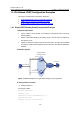
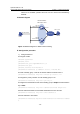
I. Network requirements
z Host A needs to access Host B on the Internet, using FE80::10 as its default
gateway.
z Switch A and Switch B belong to standby group 1 with the virtual IP address of
FE80::10.
z If Switch A operates normally, packets sent from Host A to Host B are forwarded
by Switch A; if Switch A fails, packets sent from Host A to Host B are forwarded by
Switch B.
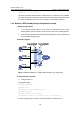
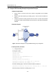
II. Network diagram
Host A
Switch A
Switch B
Virtual IPv6 address:
FE80::10
Vlan-int2
FE80::1
Vlan-int2
FE80::2
Host B
Gateway:
FE80::10
Internet
Figure 1-10 Network diagram for single VRRP standby group configuration
III. Configuration procedure
1) Configure Switch A
# Configure VLAN 2.
<SwitchA> system-view
[SwitchA] ipv6
[SwitchA] vlan 2
[SwitchA-vlan2] port GigabitEthernet 2/0/5
[SwitchA-vlan2] quit
[SwitchA] interface vlan-interface 2
[SwitchA-Vlan-interface2] ipv6 address fe80::1 link-local
[SwitchA-Vlan-interface2] ipv6 address 1::1 64
# Create a standby group 1 and set its virtual IP address to FE80::10.
[SwitchA-Vlan-interface2] vrrp ipv6 vrid 1 virtual-ip fe80::10 link-local
# Set the priority of Switch A in standby group 1 to 110.