
H3C S7500E Series Ethernet Switches Operation Manual

Operation Manual – IP Addressing and Performance
H3C S7500E Series Ethernet Switches Chapter 1 IP Addressing Configuration
1-5
1.2.2 IP Addressing Configuration Example
I. Network requirements
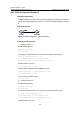
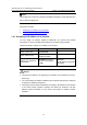
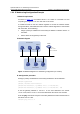
As shown in Figure 1-3, the interface VLAN 1 on a switch is connected to a LAN
comprising two segments: 172.16.1.0/24 and 172.16.2.0/24.
To enable the hosts on the two network segments to access the external network
through the switch, and enable the hosts on the two network segments to communicate
with each other, do the following:
z Assign a primary IP address and a secondary IP address to interface VLAN 1 on
the switch.
z Set the switch as the gateway on all hosts.
II. Network diagram
Vlan-int1
172.16.1.1/24
172.16.2.1/24 sub
172.16.1.0/24
172.16.1.2/24
172.16.2.0/24
172.16.2.2/24
Host A
Host B
Switch
Figure 1-3 Network diagram for IP addressing configuration (on a switch)
III. Configuration procedure
# Assign a primary IP address and a secondary IP address to VLAN-interface 1.
<Switch> system-view
[Switch] interface vlan-interface 1
[Switch-Vlan-interface1] ip address 172.16.1.1 255.255.255.0
[Switch-Vlan-interface1] ip address 172.16.2.1 255.255.255.0 sub
# Set the gateway address to 172.16.1.1 on the PCs attached to the subnet
172.16.1.0/24, and to 172.16.2.1 on the PCs attached to the subnet 172.16.2.0/24.
# Use the ping command to verify the connectivity between the switch and the hosts on
the subnet 172.16.1.0/24.
<Switch> ping 172.16.1.2