
H3C S7500E Series Ethernet Switches Operation Manual

Operation Manual – PoE
H3C S7500E Series Ethernet Switches Chapter 1 PoE Configuration
1-12
1.11 PoE Configuration Example
I. Network requirements
z The device is equipped with two PoE-supporting cards, which are inserted in Slot
3 and Slot 5 respectively. The PSE IDs are 10 and 16.
z Allocate 400 watts to PSE 10, provided the default maximum power to PSE in PSE
16 can meet the requirements.
z GigabitEthernet 3/0/1 and GigabitEthernet 3/0/2 are connected to IP telephones.
z GigabitEthernet 5/0/1 and GigabitEthernet 5/0/2 are connected to access point
(AP) devices.
z The power priority of GigabitEthernet 3/0/2 is critical.
z The power of the AP device connected to GigabitEthernet 5/0/1 does not exceed
9,000 milliwatts.
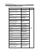
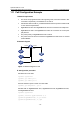
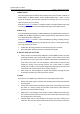
II. Network diagram
GE3/0/1
GE3/0/2
GE5/0/1
GE5/0/2
Figure 1-1 Network diagram for PoE
III. Configuration procedure
# Enable PoE for the PSE.
<Sysname> system-view
[Sysname] poe enable pse 10
[Sysname] poe enable pse 16
# Set the maximum power of PSE 10 to 400 watts.
[Sysname] poe max-power 400 pse 10
# Enable PoE on GigabitEthernet 3/0/1, GigabitEthernet 3/0/2, GigabitEthernet 5/0/1,
and GigabitEthernet 5/0/2.
<Sysname> system-view
[Sysname] interface gigabitethernet 3/0/1
[Sysname-GigabitEthernet3/0/1] poe enable
[Sysname-GigabitEthernet3/0/1] quit