
H3C S7500E Series Ethernet Switches Operation Manual

Operation Manual – RRPP
H3C S7500E Series Ethernet Switches Chapter 1 RRPP Configuration
1-17
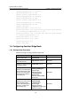
1.8.1 Configuring Single Ring Topology
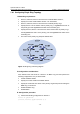
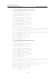
I. Networking requirements
z Device A, Device B, Device C and Device D constitute RRPP domain 1;
z Specify the control VLAN of RRPP domain 1 as VLAN 4092;
z Device A, Device B, Device C and Device D constitute primary ring 1;
z Specify Device A as the master node of primary ring 1, GigabitEthernet 3/0/1 as
the primary port and GigabitEthernet 3/0/2 as the secondary port;
z Specify Device B, Device C and Device D as the transit nodes of primary ring 1,
their GigabitEthernet 3/0/1 as the primary port and GigabitEthernet 3/0/2 as the
secondary port;
z The timers of the primary ring adopt the default value.
Figure 1-6 Single ring networking diagram
II. Configuration considerations
First, determine the node mode of a device in an RRPP ring, and then perform the
following configurations on a per-device basis:
z Create an RRPP domain.
z Specify the control VLAN for the RRPP domain.
z Specify the node mode of a device on the primary ring and the ports accessing the
RRPP ring on the device.
z Enable the RRPP ring.
z Enable RRPP
III. Configuration procedure
1) Perform the following configuration on Device A:
<Device A> system-view
[DeviceA] interface gigabitethernet 3/0/1