
H3C S7500E Series Ethernet Switches Operation Manual

Operation Manual – IP Addressing and Performance
H3C S7500E Series Ethernet Switches Chapter 2 IP Performance Configuration
2-3
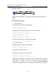
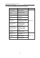
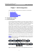
II. Network diagram
Figure 2-1 Network diagram for receiving and forwarding directed broadcasts (on a
switch)
III. Configuration procedure
z Configure Switch A
# Enable Switch A to receive directed broadcasts.
<SwitchA> system-view
[SwitchA] ip forward-broadcast
# Configure IP addresses for VLAN-interface 3 and VLAN-interface 2.
[SwitchA] interface vlan-interface 3
[SwitchA-Vlan-interface3] ip address 1.1.1.2 24
[SwitchA-Vlan-interface3] quit
[SwitchA] interface vlan-interface 2
[SwitchA-Vlan-interface2] ip address 2.2.2.2 24
# Enable VLAN-interface 2 to forward directed broadcasts.
[SwitchA-Vlan-interface2] ip forward-broadcast
z Configure Switch B
# Enable Switch B to receive directed broadcasts.
<SwitchB> system-view
[SwitchB] ip forward-broadcast
# Configure a static route to the host.
[SwitchB] ip route-static 1.1.1.1 24 2.2.2.2
# Configure an IP address for VLAN-interface 2.
[SwitchB] interface vlan-interface 2
[SwitchB-Vlan-interface2] ip address 2.2.2.1 24
After the above configurations, if you ping the subnet broadcast address (2.2.2.255) of
VLAN-interface 2 of Switch A on the host, the ping packets can be received by
VLAN-interface 2 of Switch B. However, if you disable the ip forward-broadcast
command, the ping packets can not be received by the VLAN-interface 2 of Switch B.