
H3C S7500E Series Ethernet Switches Operation Manual

Operation Manual – QinQ-BPDU Tunneling
H3C S7500E Series Ethernet Switches Chapter 2 BPDU Tunneling Configuration
2-2
II. BPDU transparent transmission
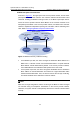
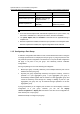
As shown in Figure 2-1, the upper part is the service provider network, and the lower
part represents the customer networks. The customer networks include network A and
network B. Enabling the BPDU tunneling function on the BPDU input/output devices
across the service provider network allows BPDUs of the customer networks to be
transparently transmitted in the service provider network, and allows each customer
network to implement independent spanning tree calculation, without interfering each
other. Refer to
Configuring BPDU Transparent Transmission.
Network
Network A Network B
Customer
networks
BPDU input/output
device
BPDU input/output
device
Service provider
network
Figure 2-1 Network hierarchy of BPDU tunneling
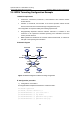
z At the BPDU input side, the device changes the destination MAC address of a
BPDU from a customer network from 0x0180-C200-0000 to a special multicast
MAC address, 0x010F-E200-0003 by default. In the service provider’s network,
the modified BPDUs are forwarded as data packets in the user VLAN.
z At the packet output side, the device recognizes the BPDU with the destination
MAC address of 0x010F-E200-0003 and restores its original destination MAC
address 0x0180-C200-0000. Then, the device removes the out-layer VLAN tag,
and sends the BPDU to the destination customer network.
Note:
Make sure, through configuration, that the VLAN tag of the BPDU is neither changed
nor removed during its transparent transmission in the service provider network;
otherwise, the system will fail to transparently transmit the customer network BPDU
correctly.