
H3C S7500E Series Ethernet Switches Operation Manual


Operation Manual – IP Source Guard
H3C S7500E Series Ethernet Switches Chapter 1 IP Source Guard Configuration
1-4
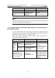
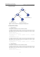
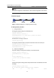
II. Network diagram
192.168.0.1/24
MAC address: 00-01-02-03-04-06
Host A
192.168.0.2/24
MAC address: 00-01-02-03-04-07
Host B
192.168.0.3/24
MAC address: 00-01-02-03-04-05
Host C
Eth2/0/1
Switch A
Eth2/0/2
Eth2/0/1 Eth2/0/2
Figure 1-1 Network diagram for configuring static binding entries
III. Configuration procedure
1) Configure Switch A
# Configure the IP addresses of various interfaces (omitted).
# Configure port Ethernet 2/0/2 of Switch A to allow only IP packets with the source
MAC address of 00-01-02-03-04-05 and the source IP address of 192.168.0.3 to pass.
<SwitchA> system-view
[SwitchA] interface ethernet 2/0/2
[SwitchA-Ethernet2/0/2] user-bind ip-address 192.168.0.3 mac-address
0001-0203-0405
[SwitchA-Ethernet2/0/2] quit
# Configure port Ethernet 2/0/1 of Switch A to allow only IP packets with the source
MAC address of 00-01-02-03-04-06 and the source IP address of 192.168.0.1 to pass.
[SwitchA] interface ethernet 2/0/1
[SwitchA-Ethernet2/0/1] user-bind ip-address 192.168.0.1 mac-address
0001-0203-0406
2) Configure Switch B
# Configure the IP addresses of various interfaces (omitted).
# Configure port Ethernet 2/0/1 of Switch B to allow only IP packets with the source
MAC address of 00-01-02-03-04-06 and the source IP address of 192.168.0.1 to pass.
<SwitchB> system-view
[SwitchB] interface ethernet 2/0/1