
H3C S7500E Series Ethernet Switches Operation Manual

Operation Manual – MSTP
H3C S7500E Series Ethernet Switches Chapter 1 MSTP Configuration
1-6
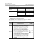
Step Description
3
The device compares the calculated configuration BPDU with the
configuration BPDU on the port of which the port role is to be defined, and
does different things according to the comparison result:
z If the calculated configuration BPDU is superior, the device will consider
this port as the designated port, and the configuration BPDU on the port
will be replaced with the calculated configuration BPDU, which will be
sent out periodically.
z If the configuration BPDU on the port is superior, the device will block this
port without updating its configuration BPDU, so that the port will only
receive BPDUs, but not send any, and will not forward data.
Note:
When the network topology is stable, only the root port and designated ports forward
traffic, while other ports are all in the blocked state – they only receive STP packets but
do not forward user traffic.
Once the root bridge, the root port on each non-root bridge and designated ports have
been successfully elected, the entire tree-shaped topology has been constructed.
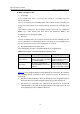
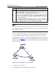
The following is an example of how the STP algorithm works. The specific network
diagram is shown in
Figure 1-2. In the feature, the priority of Device A is 0, the priority of
Device B is 1, the priority of Device C is 2, and the path costs of these links are 5, 10
and 4 respectively.
Figure 1-2 Network diagram for the STP algorithm
z Initial state of each device
The following table shows the initial state of each device.