
H3C S7500E Series Ethernet Switches Operation Manual


Operation Manual – MSTP
H3C S7500E Series Ethernet Switches Chapter 1 MSTP Configuration
1-16
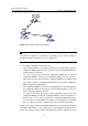
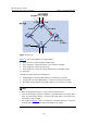
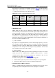
Figure 1-5 Port roles
Figure 1-5 helps understand these concepts. Where,
z Devices A, B, C, and D constitute an MST region.
z Port 1 and port 2 of device A connect to the common root bridge.
z Port 5 and port 6 of device C form a loop.
z Port 3 and port 4 of device D connect downstream to other MST regions.
11) Port states
In MSTP, port states fall into the following tree:
z Forwarding: the port learns MAC addresses and forwards user traffic;
z Learning: the port learns MAC addresses but does not forward user traffic;
z Discarding: the port neither learns MAC addresses nor forwards user traffic.
Note:
z When in different MST instances, a port can be in different states.
z The role a boundary port plays in an MSTI is consistent with the role it plays in the
CIST. The master port, which is a root port in the CIST while a master port in the
other MSTIs, is an exception.
z For example, inFigure 1-5, port 1 on switch A is a boundary port. It is a root port in
the CIST while a master port in all the other MSTIs in the region.