
H3C S7500E Series Ethernet Switches Operation Manual

Operation Manual – MSTP
H3C S7500E Series Ethernet Switches Chapter 1 MSTP Configuration
1-43
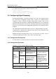
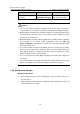
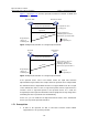
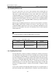
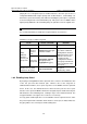
Figure 1-7 and Figure 1-8 show the rapid state transition mechanism on MSTP and
RSTP designated ports.
Root port blocks other
non-edge ports
Upstream switch Downstream switch
Root port changes to
forwarding state and sends
Agreement to upstream switch
Designated port
changes to
forwarding state
Proposal for rapid transition
Agreement
A
g
r
e
e
m
e
n
t
Root port
Designated port
Figure 1-7 Rapid state transition of a designated port in MSTP
Upstream
device
Downstream
device
Root port blocks other non-
edge ports, changes to
forwarding state and sends
Agreement to upstream device
Root port
Designated port
Proposal for rapid transition
A
g
r
e
e
m
e
n
t
Designated port
changes to
forwarding state
Figure 1-8 Rapid state transition of a designated port in RSTP
If the upstream device comes from another vendor, the rapid state transition
implementation may be limited. For example, when the upstream device adopts RSTP,
the downstream device adopts MSTP and does not support RSTP mode, the root port
on the downstream device receives no agreement packet from the upstream device
and thus sends no agreement packets to the upstream device. As a result, the
designated port of the upstream switch fails to transit rapidly and can only change to the
forwarding state after a period twice the Forward Delay.
In this case, you can enable the No Agreement Check feature on the downstream
device’s port to perform rapid state transition.
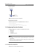
1.7.1 Prerequisites
z A device is the upstream one that is connected to another vendor’s MSTP
supported device via a point-to-point link.