
H3C S7500E Series Ethernet Switches Operation Manual

Operation Manual – MSTP
H3C S7500E Series Ethernet Switches Chapter 1 MSTP Configuration
1-50
1.10 MSTP Configuration Example
I. Network requirements
Configure MSTP so that packets of different VLANs are forwarded along different
spanning trees. The specific configuration requirements are as follows:
z All devices on the network are in the same MST region.
z Packets of VLAN 10 are forwarded along MST region 1, those of VLAN 30 are
forwarded along MST instance 3, those of VLAN 40 are forwarded along MST
instance 4, and those of VLAN 20 are forwarded along MST instance 0.
z Device A and Device B are convergence layer devices, while Device C and Device
D are access layer devices. VLAN 10 and VLAN 30 are terminated on the
convergence layer devices, and VLAN 40 is terminated on the access layer
devices, so the root bridges of MST instance 1 and MST instance 3 are Device A
and Device B respectively, while the root bridge of MST instance 4 is Device C.
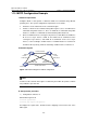
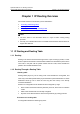
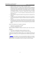
II. Network diagram
Switch A Switch B
Switch DSwitch C
Permit:all VLAN
Permit:VLAN 20,40
Permit:
VLAN 10,20
Permit:
VLAN 10,20
Permit:
VLAN 20,30
Permit:
VLAN 20,30
Figure 1-10 Network diagram for MSTP configuration
Note:
“Permit:“ beside each link in the figure is followed by the VLANs the packets of which
are permitted to pass this link.
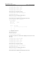
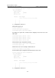
III. Configuration procedure
1) Configuration on Device A
# Enter MST region view.
<DeviceA> system-view
[DeviceA] stp region-configuration
# Configure the region name, VLAN-to-instance mappings and revision level of the
MST region.