
H3C S7500E Series Ethernet Switches Operation Manual

Operation Manual – IPv4 Routing
H3C S7500E Series Ethernet Switches Chapter 1 Static Routing Configuration
1-4
1.4 Configuration Example
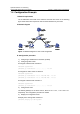
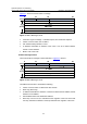
I. Network requirements
The IP addresses and masks of the switches and hosts are shown in the following
figure. Static routes are required for interconnection between any two hosts.
II. Network diagram
Figure 1-1 Network diagram for static route configuration
III. Configuration procedure
1) Configuring IP addresses for interfaces (omitted)
2) Configuring static routes
# Configure a default route on Switch A
<SwitchA> system-view
[SwitchA] ip route-static 0.0.0.0 0.0.0.0 1.1.4.2
# Configure two static routes on Switch B
<SwitchB> system-view
[SwitchB] ip route-static 1.1.2.0 255.255.255.0 1.1.4.1
[SwitchB] ip route-static 1.1.3.0 255.255.255.0 1.1.5.6
# Configure a default route on Switch C
<SwitchC> system-view
[SwitchC] ip route-static 0.0.0.0 0.0.0.0 1.1.5.5
3) Configure the hosts
The default gateways for the three hosts A, B and C are 1.1.2.3, 1.1.6.1 and 1.1.3.1
respectively. The configuration procedure is omitted.
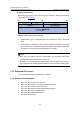
4) Display the configuration result
# Display the IP routing table of Switch A.
[SwitchA] display ip routing-table