
H3C S7500E Series Ethernet Switches Operation Manual

Operation Manual – IPv4 Routing
H3C S7500E Series Ethernet Switches Chapter 2 RIP Configuration
2-19
Note:
Since RIPv1 routing information has a long aging time, it will still exist until aged out
after RIPv2 is configured.
2.6.2 Configuring RIP Route Redistribution
I. Network requirements
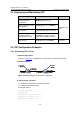
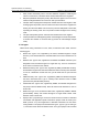
As shown in Figure 2-5, two RIP processes are running on Switch B, which
communicates with Switch A through RIP100 and with Switch C through RIP 200.
Configure route redistribution on Switch B, letting the two RIP processes redistribute
routes from each other. Set the cost of redistributed routes from RIP 200 to 3. Configure
a filtering policy on Switch B to filter out the route 4.1.1.1/24 from RIP200, making the
route not advertised to Switch A.
II. Network diagram
Figure 2-5 Network diagram for RIP route redistribution configuration
III. Configuration procedure
1) Configure an IP address for each interface (Omitted).
2) Configure basic RIP functions.
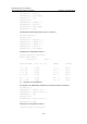
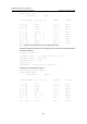
# Enable RIP 100 and specify RIP version 2 on Switch A.
<SwitchA> system-view
[SwitchA] rip 100
[SwitchA-rip-100] network 1.0.0.0
[SwitchA-rip-100] network 2.0.0.0
[SwitchA-rip-100] version 2
[SwitchA-rip-100] undo summary
[SwitchA-rip-100] quit
# Enable RIP 100 and RIP 200 and specify RIP version 2 on Switch B.
<SwitchB> system-view
[SwitchB] rip 100
[SwitchB-rip-100] network 1.0.0.0