
H3C S7500E Series Ethernet Switches Operation Manual

Operation Manual – IPv4 Routing
H3C S7500E Series Ethernet Switches Chapter 3 OSPF Configuration
3-46
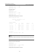
PING 10.4.1.1: 56 data bytes, press CTRL_C to break
Request time out
Reply from 10.4.1.1: bytes=56 Sequence=2 ttl=253 time=15 ms
Reply from 10.4.1.1: bytes=56 Sequence=3 ttl=253 time=1 ms
Reply from 10.4.1.1: bytes=56 Sequence=4 ttl=253 time=16 ms
Reply from 10.4.1.1: bytes=56 Sequence=5 ttl=253 time=1 ms
--- 10.4.1.1 ping statistics ---
5 packet(s) transmitted
4 packet(s) received
20.00% packet loss
round-trip min/avg/max = 1/8/16 ms
3.9.2 Configuring an OSPF Stub Area
I. Network requirements
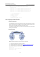
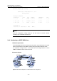
The following figure shows an AS is split into three areas, where all switches run OSPF.
Switch A and Switch B act as ABRs to forward routing information between areas.
Switch D acts as the ASBR to redistribute routes (static routes).
It is required to configure Area 1 as a Stub area, reducing LSAs to this area without
affecting route reachability.
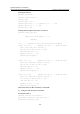
II. Network diagram
Area 0
Area 1
Stub
Area 2
Switch C
Vlan-int100
10.1.1.2/24
Vlan-int100
10.1.1.1/24
Vlan-int300
10.4.1.1/24
Vlan-int200
10.2.1.2/24
Switch B
Vlan-int200
10.3.1.1/24
Vlan-int200
10.3.1.2/24
Switch A
Vlan-int200
10.2.1.1/24
Vlan-int300
10.5.1.1/24
Switch D
ASBR
Figure 3-22 Network diagram for OSPF Stub area configuration
1) Configure IP addresses for interfaces (omitted).
2) Configure OSPF basic functions (refer to
Configuring OSPF Basic Functions).
3) Configure Switch D to redistribute static routes.
[SwitchD] ip route-static 3.1.2.1 24 10.5.1.2
[SwitchD] ospf
[SwitchD-ospf-1] import-route static
[SwitchD-ospf-1] quit