
H3C S7500E Series Ethernet Switches Operation Manual

Operation Manual – IPv4 Routing
H3C S7500E Series Ethernet Switches Chapter 4 IS-IS Configuration
4-40
4.7.2 DIS Selection Configuration
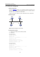
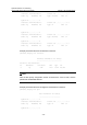
I. Network requirements
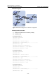
As shown in Figure 4-15, Switch A, B, C and Switch D reside in IS-IS area 10 on a
broadcast network (Ethernet). Switch A and Switch B are Level-1-2 switches, Switch C
is a Level-1 switch, and Switch D is a Level-2 switch.
Change the DIS priority of Switch A to make it selected as the Level-1-2 DIS router.
II. Network diagram
Switch A
L1/L2
Switch C
L1
Switch B
L1/L2
Switch D
L2
Vlan-int100
10.1.1.1/24
Vlan-int100
10.1.1.2/24
Vlan-int100
10.1.1.3/24
Vlan-int100
10.1.1.4/24
Figure 4-15 Network diagram for DIS selection
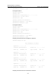
III. Configuration procedure
1) Configure an IP address for each interface (omitted)
2) Enable IS-IS
# Configure Switch A.
<SwitchA> system-view
[SwitchA] isis 1
[SwitchA-isis-1] network-entity 10.0000.0000.0001.00
[SwitchA-isis-1] quit
[SwitchA] interface vlan-interface 100
[SwitchA-Vlan-interface100] isis enable 1
[SwitchA-Vlan-interface100] quit
# Configure Switch B.
<SwitchB> system-view
[SwitchB] isis 1
[SwitchB-isis-1] network-entity 10.0000.0000.0002.00
[SwitchB-isis-1] quit
[SwitchB] interface vlan-interface 100
[SwitchB-Vlan-interface100] isis enable 1