
H3C S7500E Series Ethernet Switches Operation Manual

Operation Manual – IPv4 Routing
H3C S7500E Series Ethernet Switches Chapter 5 BGP Configuration
5-43
* i 9.1.3.0/24 9.1.3.1 0 100 0 ?
*>i 200.1.1.0 9.1.3.1 0 100 0 ?
You can find the route 8.0.0.0 becomes valid with the next hop being Switch A.
# Ping 8.1.1.1 on Switch C.
[SwitchC] ping 8.1.1.1
PING 8.1.1.1: 56 data bytes, press CTRL_C to break
Reply from 8.1.1.1: bytes=56 Sequence=1 ttl=254 time=31 ms
Reply from 8.1.1.1: bytes=56 Sequence=2 ttl=254 time=47 ms
Reply from 8.1.1.1: bytes=56 Sequence=3 ttl=254 time=31 ms
Reply from 8.1.1.1: bytes=56 Sequence=4 ttl=254 time=16 ms
Reply from 8.1.1.1: bytes=56 Sequence=5 ttl=254 time=31 ms
--- 8.1.1.1 ping statistics ---
5 packet(s) transmitted
5 packet(s) received
0.00% packet loss
round-trip min/avg/max = 16/31/47 ms
5.9.2 BGP and IGP Synchronization Configuration
I. Network requirements
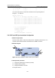
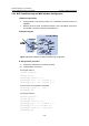
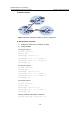
As shown below, OSPF is used as the IGP protocol in AS65009, where Switch C is a
non-BGP switch. Between Switch A and Switch B is an EBGP connection.
II. Network diagram
Figure 5-17 Network diagram for BGP and IGP synchronization
III. Configuration procedure
1) Configure IP addresses for interfaces (omitted)
2) Configure OSPF (omitted)
3) Configure the EBGP connection
# Configure Switch A.