
H3C S7500E Series Ethernet Switches Operation Manual

Operation Manual – IPv4 Routing
H3C S7500E Series Ethernet Switches Chapter 5 BGP Configuration
5-46
5.9.3 BGP Load Balancing and MED Attribute Configuration
I. Network requirements
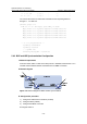
z Configure BGP on all switches; Switch A is in AS65008, and Switch B and C in
AS65009.
z Between Switch A and B, and between Switch A and C are EBGP connections,
and an IBGP connection is between Switch B and C.
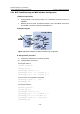
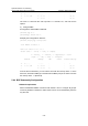
II. Network diagram
Figure 5-18 Network diagram for BGP load balancing configuration
III. Configuration procedure
1) Configure IP addresses for interfaces (omitted)
2) Configure BGP connections
# Configure Switch A.
<SwitchA> system-view
[SwitchA] bgp 65008
[SwitchA-bgp] router-id 1.1.1.1
[SwitchA-bgp] peer 200.1.1.1 as-number 65009
[SwitchA-bgp] peer 200.1.2.1 as-number 65009
# Inject route 8.0.0.0/8 to BGP routing table.
[SwitchA-bgp] network 8.0.0.0 255.0.0.0
[SwitchA-bgp] quit
# Configure Switch B.
<SwitchB> system-view
[SwitchB] bgp 65009
[SwitchB-bgp] router-id 2.2.2.2
[SwitchB-bgp] peer 200.1.1.2 as-number 65008
[SwitchB-bgp] peer 9.1.1.2 as-number 65009
[SwitchB-bgp] network 9.1.1.0 255.255.255.0
[SwitchB-bgp] quit