
H3C S7500E Series Ethernet Switches Operation Manual

Operation Manual – IPv4 Routing
H3C S7500E Series Ethernet Switches Chapter 5 BGP Configuration
5-54
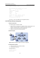
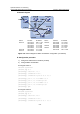
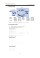
II. Network diagram
Device Interface IP address Device Interface IP address
Switch A Vlan-int100 200.1.1.1/24 Switch D Vlan-int400 10.1.3.2/24
Vlan-int200 10.1.1.1/24 Vlan-int200 10.1.5.1/24
Vlan-int300 10.1.2.1/24 Switch E Vlan-int500 10.1.4.2/24
Vlan-int400 10.1.3.1/24 Vlan-int200 10.1.5.2/24
Vlan-int500 10.1.4.1/24 Switch F Vlan-int200 9.1.1.1/24
Switch B Vlan-int200 10.1.1.2/24 Vlan-int100 200.1.1.2/24
Switch C Vlan-int300 10.1.2.2/24
Figure 5-21 Network diagram for BGP confederation configuration (on switches)
III. Configuration procedure
1) Configure IP addresses for interfaces (omitted)
2) Configure BGP confederation
# Configure Switch A.
<SwitchA> system-view
[SwitchA] bgp 65001
[SwitchA-bgp] router-id 1.1.1.1
[SwitchA-bgp] confederation id 200
[SwitchA-bgp] confederation peer-as 65002 65003
[SwitchA-bgp] peer 10.1.1.2 as-number 65002
[SwitchA-bgp] peer 10.1.1.2 next-hop-local
[SwitchA-bgp] peer 10.1.2.2 as-number 65003
[SwitchA-bgp] peer 10.1.2.2 next-hop-local
[SwitchA-bgp] quit
# Configure Switch B.
<SwitchB> system-view
[SwitchB] bgp 65002
[SwitchB-bgp] router-id 2.2.2.2
[SwitchB-bgp] confederation id 200
[SwitchB-bgp] confederation peer-as 65001 65003