
H3C S7500E Series Ethernet Switches Operation Manual

Operation Manual – Multicast
H3C S7500E Series Ethernet Switches Chapter 3 Multicast VLAN Configuration
3-1
Chapter 3 Multicast VLAN Configuration
3.1 Introduction to Multicast VLAN
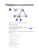
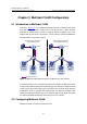
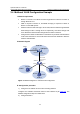
As shown in Figure 3-1, in the traditional multicast programs-on-demand mode, when
hosts that belong to different VLANs, Host A, Host B and Host C require multicast
programs on demand service, Router A needs to forward a separate copy of the
multicast data in each VLAN. This results in not only waste of network bandwidth but
also extra burden on the Layer 3 device.
Multicast packet transmission
without Multicast VLAN
Source
Router A
Multicast packets
Multicast packet transmission
when Multicast VLAN runs
Source
Router A
Switch A
Host A
Receiver
Host B
Receiver
Host C
Receiver
VLAN 30
VLAN 20
VLAN 10
Switch A
Host A
Receiver
Host B
Receiver
Host C
Receiver
VLAN 30
VLAN 20
VLAN 10
Figure 3-1 Before and after multicast VLAN is enabled on the Layer 2 device
To solve this problem, you can enable the multicast VLAN feature on Switch A, namely
configure the VLANs to which these hosts belong as sub-VLANs of a multicast VLAN
on the Layer 2 device and enable Layer 2 multicast in the multicast VLAN. After this
configuration, Router A replicates the multicast data only within the multicast VLAN
instead of forwarding a separate copy of the multicast data to each VLAN. This saves
the network bandwidth and lessens the burden of the Layer 3 device.
3.2 Configuring Multicast VLAN
Follow these steps to configure a multicast VLAN: