
H3C S7500E Series Ethernet Switches Operation Manual


Operation Manual – Multicast
H3C S7500E Series Ethernet Switches Chapter 3 Multicast VLAN Configuration
3-3
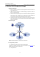
3.4 Multicast VLAN Configuration Example
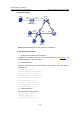
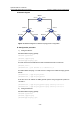
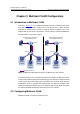
I. Network requirements
z Router A connects to a multicast source through Ethernet 1/0/2 and to Switch A,
through Ethernet 1/0/1.
z IGMP is required on Router A, and IGMP Snooping is required on Switch A.
Router A is the IGMP querier.
z Switch A’s Ethernet 2/0/1 belongs to VLAN 1024, Ethernet 2/0/2 through Ethernet
2/0/4 belong to VLAN 11 through VLAN 13 respectively, and Host A through Host
C are attached to Ethernet 2/0/2 through Ethernet 2/0/4 of Switch A.
z Configure the multicast VLAN feature so that Router A just sends multicast data to
VLAN 1024 rather than to each VLAN when the three hosts attached to Switch A
need the multicast data.
II. Network diagram
Source
Router A
Switch A
Host A
Receiver
Host B
Receiver
Host C
Receiver
Eth2/0/2
Eth2/0/3
Vlan-int1024
10.110.1.2/24
Eth2/0/1
VLAN 13VLAN 11
Eth2/0/4
1.1.1.1/24
Eth1/0/2
1.1.1.2/24
Eth1/0/1
10.110.1.1/24
VLAN 12
VLAN 1024
IGMP querier
Figure 3-2 Network diagram for multicast VLAN configuration
III. Configuration procedure
1) Configure an IP address for each interconnecting interface
Configure an IP address and subnet mask for each interface as per
Figure 3-2. The
detailed configuration steps are omitted here.
2) Configure Router A