
H3C S7500E Series Ethernet Switches Operation Manual

Operation Manual – Multicast
H3C S7500E Series Ethernet Switches Chapter 4 IGMP Configuration
4-15
4.6 IGMP Configuration Example
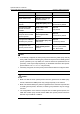
I. Network requirements
z Receivers receive VOD information through the multicast mode. Receivers of
different organizations form stub networks N1 and N2, and Host A and Host C are
receivers in N1 and N2 respectively.
z Switch A in the PIM network connects to N1, and both Switch B and Switch C
connect to N2.
z Switch A connects to N1 through VLAN-interface 100, and to other devices in the
PIM network through VLAN-interface 101.
z Switch B and Switch C connect to N2 through their respective VLAN-interface 200,
and to other devices in the PIM network through VLAN-interface 201 and
VLAN-interface 202 respectively.
z IGMP is required between Switch A and N1. IGMP is required between the other
two switches and N2, with Switch B as the IGMP querier.
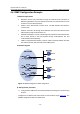
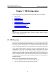
II. Network diagram
Ethernet Ethernet
Figure 4-3 Network diagram for IGMP configuration
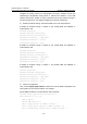
III. Configuration procedure
1) Configure the IP addresses of the switch interfaces and configure a unicast routing
protocol
Configure the IP address and subnet mask of each interface as per
Figure 4-3. The
detailed configuration steps are omitted here.