
H3C S7500E Series Ethernet Switches Operation Manual

Operation Manual – Multicast
H3C S7500E Series Ethernet Switches Chapter 5 PIM Configuration
5-40
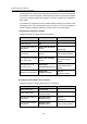
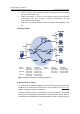
z Switch A connects to stub network N1 through VLAN-interface 100, and to Switch
D through VLAN-interface 103.
z Switch B and Switch C connect to stub network N2 through their respective
VLAN-interface 200, and to Switch D through VLAN-interface 101 and
VLAN-interface 102 respectively.
z IGMPv2 is to run between Switch A and N1, and between Switch B/Switch C and
N2.
II. Network diagram
Ethernet
EthernetEthernet
N1N2
Vlan-
i
n
t10
2
Vlan-i
nt1
02
Vl
a
n-int10
3
Vlan-i
nt
103
Device Interface IP address Device Interface IP address
Switch A Vlan-int100 10.110.1.1/24 Switch D Vlan-int300 10.110.5.1/24
Vlan-int103 192.168.1.1/24 Vlan-int103 192.168.1.2/24
Switch B Vlan-int200 10.110.2.1/24 Vlan-int101 192.168.2.2/24
Vlan-int101 192.168.2.1/24 Vlan-int102 192.168.3.2/24
Switch C Vlan-int200 10.110.2.2/24
Vlan-int102 192.168.3.1/24
Figure 5-10 Network diagram for PIM-DM configuration
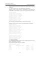
III. Configuration procedure
1) Configure the interface IP addresses and unicast routing protocol for each switch
Configure the IP address and subnet mask for each interface as per
Figure 5-10.
Detailed configuration steps are omitted here.
Configure the OSPF protocol for interoperation among the switches in the PIM-DM
domain. Ensure the network-layer interoperation among Switch A, Switch B, Switch C
and Switch D in the PIM-DM domain and enable dynamic update of routing information