
H3C S7500E Series Ethernet Switches Operation Manual

Operation Manual – Multicast
H3C S7500E Series Ethernet Switches Chapter 5 PIM Configuration
5-50
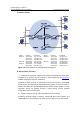
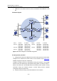
# Enable IP multicast routing on Switch A, enable PIM-SM on each interface, and
enable IGMPv3 on VLAN-interface 100, which connects Switch A to the stub network.
<SwitchA> system-view
[SwitchA] multicast routing-enable
[SwitchA] interface vlan-interface 100
[SwitchA-Vlan-interface100] igmp enable
[SwitchA-Vlan-interface100] igmp version 3
[SwitchA-Vlan-interface100] pim sm
[SwitchA-Vlan-interface100] quit
[SwitchA] interface vlan-interface 101
[SwitchA-Vlan-interface101] pim sm
[SwitchA-Vlan-interface101] quit
[SwitchA] interface vlan-interface 102
[SwitchA-Vlan-interface102] pim sm
[SwitchA-Vlan-interface102] quit
The configuration on Switch B and Switch C is similar to that on Switch A. The
configuration on Switch D and Switch E is also similar to that on Switch A except that it
is not necessary to enable IGMP on the corresponding interfaces on these two
switches.
3) Configure the SSM group range
# Configure the SSM group range to be 232.1.1.0/24 one Switch A.
[SwitchA] acl number 2000
[SwitchA-acl-basic-2000] rule permit source 232.1.1.0 0.0.0.255
[SwitchA-acl-basic-2000] quit
[SwitchA] pim
[SwitchA-pim] ssm-policy 2000
[SwitchA-pim] quit
The configuration on Switch B, Switch C, Switch D and Switch E is similar to that on
Switch A.
4) Verify the configuration
Carry out the display pim interface command to view the PIM configuration and
running status on each interface. For example:
# View the PIM configuration information on Switch A.
[SwitchA] display pim interface
Interface NbrCnt HelloInt DR-Pri DR-Address
Vlan100 0 30 1 10.110.1.1 (local)
Vlan101 1 30 1 192.168.1.2
Vlan102 1 30 1 192.168.9.2
Assume that Host A needs to receive the information a specific multicast source S
(10.110.5.100/24) sends to multicast group G (232.1.1.1/24). Switch A builds an SPT