
H3C S7500E Series Ethernet Switches Operation Manual

Operation Manual – Multicast
H3C S7500E Series Ethernet Switches Chapter 6 MSDP Configuration
6-18
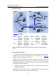
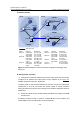
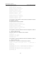
II. Network diagram
Vlan-int103
Vlan-int103
Vl
a
n-int20
0
Vlan-
int30
0
Vl
an-
int40
0
Device Interface IP address Device Interface IP address
Switch A Vlan-int103 10.110.1.2/24 Switch D Vlan-int104 10.110.4.2/24
Vlan-int100 10.110.2.1/24 Vlan-int300 10.110.5.1/24
Vlan-int200 10.110.3.1/24 Switch E Vlan-int105 10.110.6.1/24
Switch B Vlan-int103 10.110.1.1/24 Vlan-int102 192.168.3.2/24
Vlan-int101 192.168.1.1/24 Loop0 3.3.3.3/32
Loop0 1.1.1.1/32 Switch F Vlan-int105 10.110.6.2/24
Switch C Vlan-int104 10.110.4.1/24 Vlan-int400 10.110.7.1/24
Vlan-int102 192.168.3.1/24 Source 1 — 10.110.2.100/24
Vlan-int101 192.168.1.2/24 Source 2 — 10.110.5.100/24
Loop0 2.2.2.2/32
Figure 6-5 Network diagram for inter-AS multicast configuration leveraging BGP
routes
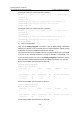
III. Configuration procedure
1) Configure the interface IP addresses and unicast routing protocol for each switch
Configure the IP address and subnet mask for each interface as per
Figure 6-5.
Detailed configuration steps are omitted here.
Configure OSPF for interconnection between switches in each AS. Ensure the
network-layer interoperation among each AS, and ensure the dynamic update of
routing information between the switches through a unicast routing protocol. Detailed
configuration steps are omitted here.
2) Enable IP multicast routing, enable PIM-SM on each interface, and configure a
PIM-SM domain border
# Enable IP multicast routing on Switch A, enable PIM-SM on each interface, and
enable IGMP on the host-side interface VLAN-interface 200.