
H3C S7500E Series Ethernet Switches Operation Manual


Operation Manual – Multicast
H3C S7500E Series Ethernet Switches
Chapter 7 Multicast Routing and Forwarding
Configuration
7-15
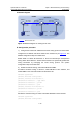
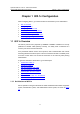
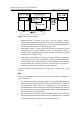
II. Network diagram
Switch A Switch B Switch C
Vlan-int102
30.1.1.2/24
Vlan-int101
20.1.1.2/24
Vlan-int101
20.1.1.1/24
Vlan-int102
30.1.1.1/24
Source 1Source 2 Receiver
40.1.1.100/24 10.1.1.100/24
Multicast static route
Vlan-int200
40.1.1.1/24
Vlan-int100
10.1.1.1/24
OSPF domain
PIM-DM
50.1.1.100/24
Vlan-int300
50.1.1.1/24
Figure 7-4 Network diagram for creating an RPF route
III. Configuration procedure
1) Configure the interface IP addresses and unicast routing protocol for each switch
Configure the IP address and subnet mask for each interface as per
Figure 7-4. The
detailed configuration steps are omitted here.
Enable OSPF on Switch B and Switch C. Ensure the network-layer interoperation
among Switch B and Switch C. Ensure that the switches can dynamically update their
routing information by leveraging the unicast routing protocol. The specific
configuration steps are omitted here.
2) Enable IP multicast routing, and enable PIM-DM and IGMP
# Enable IP multicast routing on Switch C, enable PIM-DM on each interface, and
enable IGMP on the host-side interface VLAN-interface 100.
<SwitchC> system-view
[SwitchC] multicast routing-enable
[SwitchC] interface vlan-interface 100
[SwitchC-Vlan-interface100] igmp enable
[SwitchC-Vlan-interface100] pim dm
[SwitchC-Vlan-interface100] quit
[SwitchC] interface vlan-interface 101
[SwitchC-Vlan-interface101] pim dm
[SwitchC-Vlan-interface101] quit
# Enable IP multicast routing on Switch A and enable PIM-DM on each interface.
<SwitchA> system-view
[SwitchA] multicast routing-enable