
H3C S7500E Series Ethernet Switches Operation Manual

Operation Manual – VLAN
H3C S7500E Series Ethernet Switches Chapter 1 VLAN Configuration
1-2
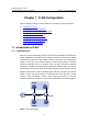
A VLAN is not restricted by physical factors, that is to say, hosts that reside in different
network segments may belong to the same VLAN, users in a VLAN can be connected
to the same switch, or span across multiple switches or routers.
VLAN technology has the following advantages:
1) Broadcast traffic is confined to each VLAN, reducing bandwidth utilization and
improving network performance.
2) LAN security is improved. Packets in different VLANs cannot communicate with
each other directly. That is, users in a VLAN cannot interact directly with users in
other VLANs, unless routers or Layer 3 switches are used.
3) A more flexible way to establish virtual working groups. With VLAN technology,
clients can be allocated to different working groups, and users from the same
group do not have to be within the same physical area, making network
construction and maintenance much easier and more flexible.
1.1.2 VLAN Fundamental
To enable packets being distinguished by the VLANs they belong to, a field used to
identify VLANs is added to packets. As common switches operate on the data link layer
of the OSI model, they only process Layer 2 encapsulation information and the field
thus needs to be inserted to the Layer 2 encapsulation information of packets.
The format of the packets carrying the fields identifying VLANs is defined in IEEE
802.1Q, which is issued in 1999.
In the header of a traditional Ethernet packet, the field following the destination MAC
address and the source MAC address is protocol type, which indicates the upper layer
protocol type.
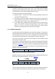
Figure 1-2 illustrates the format of a traditional Ethernet packet, where
DA stands for destination MAC address, SA stands for source MAC address, and Type
stands for upper layer protocol type.
Figure 1-2 The format of a traditional Ethernet packet
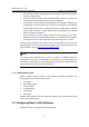
IEEE802.1Q defines a four-byte VLAN Tag field between the DA&SA field and the Type
field to carry VLAN-related information, as shown in
Figure 1-3.
Figure 1-3 The position and the format of the VLAN Tag field
The VLAN Tag field comprises four sub-fields: the tag protocol identifier (TPID) field,
the Priority field, the canonical format indicator (CFI) field, and the VLAN ID field.