
H3C S7500E Series Ethernet Switches Operation Manual

Operation Manual – Portal
H3C S7500E Series Ethernet Switches Chapter 1 Portal Configuration
1-12
1.8 Portal Configuration Examples
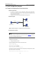
1.8.1 Example for Configuring Direct Portal Authentication
I. Network requirements
z The switch is configured for direct authentication. Before portal authentication,
users can access only the portal server. After passing portal authentication, they
can access external networks.
z A RADIUS server serves as the authentication/accounting server.
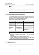
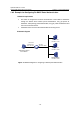
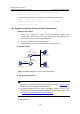
II. Network diagram
RADIUS server
Switch
Host
2.2.2.2/24
Gateway:2.2.2.1/24
Vlan-int100
2.2.2.1/24
Vlan-int2
192.168.0.100/24
Portal server
192.168.0.111/24
192.168.0.112/24
Figure 1-4 Network diagram for configuring direct portal authentication
III. Configuration procedure
Note:
You need to configure IP addresses for the devices as shown in Figure 1-4 and ensure
that routes are available between devices.
Configure the access device:
1) Configure a RADIUS scheme
# Create a RADIUS scheme named rs1 and enter its view.
<Switch> system-view
[Switch] radius scheme rs1
# Set the server type to extended.
[Switch-radius-rs1] server-type extended
# Configure the primary authentication server, the primary accounting server, and the
keys for the servers to communicate.
[Switch-radius-rs1] primary authentication 192.168.0.112