
H3C S7500E Series Ethernet Switches Operation Manual

Operation Manual – ARP
H3C S7500E Series Ethernet Switches Chapter 2 Proxy ARP Configuration
2-4
[SwitchB-vlan2] port gigabitethernet 2/0/1
[SwitchB-vlan2] port gigabitethernet 2/0/2
[SwitchB-vlan2] port gigabitethernet 2/0/3
[SwitchB-vlan2] quit
[SwitchB] interface gigabitethernet 2/0/2
[SwitchB-GigabitEthernet2/0/2] port-isolate enable
[SwitchB-GigabitEthernet2/0/2] quit
[SwitchB] interface gigabitethernet 2/0/3
[SwitchB-GigabitEthernet2/0/3] port-isolate enable
[SwitchB-GigabitEthernet2/0/3] quit
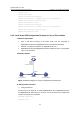
2) Configure Switch A
# Configure an IP address of VLAN-interface 2.
[SwitchA] vlan 2
[SwitchA-vlan2] port gigabitethernet 2/0/2
[SwitchA-vlan2] quit
[SwitchA] interface vlan-interface 2
[SwitchA-Vlan-interface2] ip address 192.168.10.100 255.255.0.0
Ping Host B on Host A to verify that the two hosts cannot be pinged through, which
indicates they are isolated at Layer 2.
# Configure local proxy ARP to let Host A and Host B communicate at Layer 3.
[SwitchA-Vlan-interface2] local-proxy-arp enable
[SwitchA-Vlan-interface2] quit
Ping Host B on Host A to verify that the two hosts can be pinged through, which
indicates Layer 3 communication is implemented.
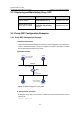
2.4.3 Local Proxy ARP Configuration Example in Isolate-user-vlan
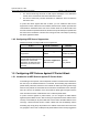
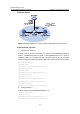
I. Network requirements
z Switch A is attached to Switch B through GigabitEthernet 2/0/1.
z VLAN 5 on Switch B is an isolate-user-vlan, which includes uplink port
GigabitEthernet 2/0/1 and two secondary VLANs (VLAN 2 and VLAN 3).
GigabitEthernet 2/0/2 belongs to VLAN 2, and GigabitEthernet 2/0/3 belongs to
VLAN 3.
z Configure local proxy ARP on Switch A to implement Layer 3 communication
between VLAN 2 and VLAN 3.